
I will first confess that I have not done a lot of hard research on this topic. I simply don’t have the time. The question has come up so often that I thought I would just brain-dump what I do know. Think of this article as “How I would design my own house”. Not necessarily how you should do it and I’m certainly not critiquing anyone who chooses to do it differently.
First, I really try to avoid calling them “conditioned attics” unless I’m able to do the Dr. Evil air quotes while I’m saying it. To me, “conditioned space” is somewhere you would want to spend a lot of time and be comfortable and therefor provide heated and cooled air. The reason we condition our homes is to be comfortable. Yes, these attics are within the conditioned boundary, the thermal envelope, etc. That doesn’t mean they are or need to be provided with supply air. The stud space between interior walls is inside the conditioned envelope as well, but I see no need to blow expensive supply air into my wall cavities. Why waste perfectly good conditioned air where no one will spend any time? These, like an encapsulated attic, are “indirectly conditioned spaces”. They are conditioned by conduction and convection from “directly conditioned space”. Yes, the mechanical code does refer to “conditioned attics”, but I think that is to easily indicate that they are unvented with the primary insulation is above the attic rather than at the home’s ceiling. I do not think that the mechanical code is implying that these attics are or need to be kept at a certain temperature. I do recall there being a code saying that you should not provide conditioned air to a space unless it had a certain fire rating, which amounted to sheet rock over the insulation and framing. I suggest you research that in your area.
I know that in California the energy code (Title 24, part 6) gives you a big energy savings credit for having your ducts in “conditioned space” over having them in an unvented, insulated (encapsulated) attic. So, many people say, “Well, if we just put a supply register up there, we can call it conditioned space and take the credit.” Last time I checked, the folks in charge frowned on that. This topic really, really needs to be clarified.
I personally do not think it is a good idea to share attic air with the house no matter how well sealed and insulated it is. Now, I’m talking about an attic where, when looking into it, you can see the insulation at the roof deck and you can see the backside of the sheet rock on the ceiling and all the wood framing and wiring and such. Is that a place you would want to spend a lot of time, even if it was a comfortable temperature? If your child wanted to move their bedroom into the attic, would you let them? I wouldn’t, unless it was sheet rocked, taped, textured, painted and provided with lights, ventilation, a safe ladder/stairs, etc. But then it would no longer be an “attic”, would it?
My point is that the air quality in an attic is questionable, at best. There is still a lot of discussion over the safety of spray-on polyurethane foam insulation (SPF) and off-gassing. Which is how most people encapsulate their attic. Even if you used a different type of insulation, would you want to breathe that? Putting a supply register in the attic without any exhaust ventilation in the attic is basically forcing attic air into your house. Even worse is putting a return grille in your attic. By the way, I would seal my ducts extra well.
If it were my house I would ensure a one-way path of airflow from the house to the attic then outside, never from the attic to the house. ASHRAE 62.2 provides guidance on ventilating homes for indoor air quality (IAQ). It requires a certain amount of outside air to be introduced to the home. Though it can be combined with local exhaust for bathrooms and kitchens, I prefer not to. It can be a relatively small, continuous flow of air into and/or out of the house (supply, exhaust, or balanced). It needs to have a switch to turn it off in case of poor outdoor air quality.
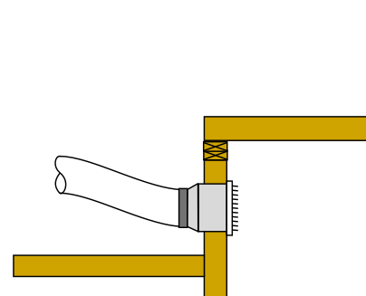
This is how I would do it if I were designing my own house with an encapsulated attic: I would provide continuous supply ventilation to an extra deep return boot as shown in the diagram, below. I would only deliver just enough to satisfy the ASHRAE 62.2 requirements for OA. I would also put a fan of the same size, maybe a little bigger, in the attic to exhaust the attic air to outside. This would ensure that the house is positively pressurized relative to the attic. If the house were super tight, I would put a pressure relief grille in the ceiling between the house and the attic with a backdraft damper. I would try to put it at the opposite end of the attic from the attic exhaust fan. Having house air exhaust through the attic would help keep the attic closer to house temperature without wasting supply air. One could argue that this is balanced ventilation because it provides both supply and exhaust to/from the house, which ASHRAE 62.2 allows you to deliver even less than just supply or exhaust. I’m not against outside air. I just think that dilution is not the only solution to pollution.

Some comments on this type of supply OA ventilation: It is much preferred over the more common exhaust ventilation because you know exactly where the air is coming from. It is unconditioned air, so you don’t want it to blow on people or have it affect the thermostat prematurely, and it has to be filtered. I’ve designed systems like this that were installed in production homes. One time I asked a homeowner how often they changed the little filter. They said, “Oh, we never have to. It never gets dirty!” I reminded them that the dirt collects on the back side – the side you can’t see. They said, “Oh. I better go check it.” Dumping the outside air here allows it to be very well distributed in the house when the system is running, which, if properly sized, should run a lot on really hot or cold days. Dumping it upstream of the main filter has the advantage of greatly reducing the impact of the main system blower fan increasing outside airflow.
I’d love to hear how you would do it in your own house and why.
Russ
—————————————————————–
Addendum, based on feedback from colleagues:
A couple points that I should have made clearer in the post:
- This is for a hypothetical new construction house that I might build on our property in northern CA (hot-dry climate).
- It would be an accessory dwelling unit (ADU) of about 1200 sf. I would make sure that the house and roof deck are very well sealed. Since the house is only 1200 sf and 3 bedroom with balanced ventilation. The minimum continuous OA rate is only around 50 cfm.
The supply fan is continuously pushing fresh air into the house. The exhaust fan in the attic is continuously pulling air from the house via the one-way damper in the ceiling, across the attic and out. They are on the same switch in case they need to be turned off, but the are intended to run continuously. The two fans would be essentially balanced and the house and attic would be essentially neutral pressure. I was weighing whether it would be better to have the fan in the house or attic be slightly larger. I’m opting for the attic fan to be slightly larger. I would size the one-way damper so that the attic is slightly more negative than the house.
The main reason I proposed this type of system is as an alternative to putting a supply register in the attic, but I think it has a lot of interesting benefits. The fact that you are pulling a continuous flow of house air across the attic makes it more likely that the attic is close to the house in temperature without wasting supply air. It’s a balanced ventilation system that avoids the cost, complexity and maintenance of an ERV/HRV. It provides continuous attic ventilation. Most people who install ERV/HRVs want to pull air from the bathrooms, not the attic.
All that being said, I think this ventilation design in this house would work fine in any climate, maybe not in a larger or more complex house. Regarding the unconditioned OA being dumped behind the return grille in a hallway, an idea I’ve toyed with (in case there was a complaint in the homes we did this in) is some sort of one-way damper on the return grille to force the OA to go up into the ducts rather than down through the grille. I think the air would be dispersed enough to not be noticed on mild days. I’d have to think about the potential for condensation inside the ducts in very humid climates. Perhaps a dehumidistat behind the return grille that turns on the central fan if it gets above a certain humidity.


 HVAC 1.0 Book – Introduction to Residential HVAC Systems
 Kwik Model 3D HVAC Design Software