If you are enjoying these posts and learning something, you may enjoy my class, “HVAC 1.0 – Introduction to Residential HVAC“. I will be adding more classes and dates regularly, please subscribe to my newsletter, The Sierra B.S. Newsletter. (B.S. stands for building science, of course) by sending an e-mail to info@sierrabuildingscience.com. If you know anyone who may benefit from this kind of information, please pass it along.
Today’s topic is Duct Siz vs. Airflow. This is Part 1 of a two or three part series on this topic.
One of the big misconceptions about airflow is how to determine how much air will flow through a certain size duct, or conversely, determining what size duct you need to deliver a certain airflow. You would not believe the range of flows I have heard as “rules of thumb”. This assumes that you have done the calculations necessary to determine how much air is needed in a room. That will be a different series of blog posts, to be sure.
Duct sizing is covered very well in ACCA Manual D and is fairly straightforward. For now just suffice it to say that there is a very important number called “Friction Rate” that determines the relationship between duct size and airflow. Friction rate describes the average pressure drop per 100 feet of duct in a system. Notice that this number is unique to a system, not just an individual duct run. For example, all things being equal, an 8” duct at the end of a long convoluted duct system will not deliver as much air as an 8” duct on a very short straight system. This is because everything that the air passes through has an impact on how much air comes out of the very end. Friction rate is a wonderful number because it takes into account how much static pressure you fan is providing, how much of that is left after you subtract out the big-ticket items like the coil, filter, supply registers and return grilles.

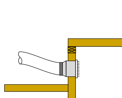
A common system configuration.
But, you say, most systems do not have runs that are 100 feet long! What use is that number that is “per 100 feet”? Actually, if you look at something called “equivalent lengths” a duct run can be well over 100 feet “long”. Equivalent lengths are numbers that can be looked up in an appendix of ACCA Manual D. This is where a fitting such as a t-wye or elbow is assigned a number that represents a length of straight duct that that has an equal pressure drop. For example a t-wye might have an equivalent length of 10 feet. A ninety degree elbow might have an equivalent length of 15 feet. A round start collar coming off of a sheet metal supply plenum can have equivalent lengths approaching 30 feet or more. When you add up the actual lengths and the equivalent lengths, it adds up quickly.
Even if the length of the run is very short, you can still use friction rate because the 100 feet is just a number they decided to use. They could have used pressure drop per 10 feet or even 1 foot. It just adds more decimal places. Don’t dwell on it. Move on. Get over it. Just don’t forget about it. One of the biggest mistakes I’ve seen contractors make is to confuse total operating static pressure (inches of water column) with friction rate (inches of water column lost per 100 feet).
The details of how to calculate friction rates are covered later, but a very common friction rate for a reasonably well-designed designed system is 0.1 iwc/100’. You can take that number and using a duct slide rule, duct calculator, or friction rate chart and determine duct size for a given airflow or determine how much air will come out of a given size duct.

Table 1 – Duct Size vs. Airflow at a Friction Rate of 0.1
Table 1 is an example of the airflow that you would get from various size vinyl flex ducts in a system with a friction rate of 0.1 iwc/100’.
Now, I’m taking a huge risk by putting this table out there and I will probably get a lot of grief for it, but here it is. The danger is using it on systems where the friction rate is something other than 0.1. (I use this table all of the time as a first guess, ball park number and it works fine. Of course, I fine-tune the calculations later, but it’s always pretty close. It’s a hundred times better than some of the numbers I’ve heard contractors rattling off.)
One of the first comments I used to get on my designs was that odd size ducts are not used. Did I mention that I have done about 2000 residential HVAC designs? Ninety-nine percent of them were for medium to large production home builders. What they meant to say was that odd size ducts are not normally stocked by their local wholesaler. That’s because none of the contractors used them. Supply, demand, etc., etc.
What if you did a detailed load calculation (ACCA Manual J), carefully selected equipment (Manual S), and knew exactly how much air each room needed. Now you are in the process of sizing ducts (Manual D). Let’s say that you had a room that needed 95 cfm. If you were a contractor who did not use odd size ducts, your choice would be between a 6″ duct, which does not give you enough air, or an 8″ duct with gives you almost twice what you need. Which would it be? Six inch, of course.
NO!
Suck it up and use 7″ duct, cheap skate!
 Here’s some other interesting ways to use this table. If you have a room that needs 197 cfm and another right next to it that needs 72 cfm what kind of t-wye will you need to serve these two rooms? To deliver at least 72 cfm, you will need a 6″ duct. To deliver at least 197 cfm you will need at least a 9″ duct. The trunk that serves these two ducts needs to be able to deliver 72 + 197 = 269 cfm. Using Table 1, that means a 10″ trunk. By the way, a duct that is split into more than one duct is called a “trunk”, just like a tree. Ducts that are on the end of a trunk and terminate in a register are called . . . branches! How about that? And that’s why we call registers “leaves”. Just kidding. Nobody does that.
So, the t-wye will need to be a what is commonly referred to as a 10-9-6 sheet metal t-wye. Any contractor who complains about this not being and “off-the-shelf” fitting probably has not done many installs from a carefully designed plan. If they really complain, just tell them to round the odd sizes UP, Making this a 10-10-6 t-wye.
Next: Part 2 – Why two 6″ ducts will not deliver the same air as one 12″ duct. Seems obvious, doesn’t it. Stay tuned.
Again, all of these blog posts are based on the training materials and topics covered in my HVAC 1.0 Class. If you know anyone who might benefit from this kind of information, please refer them to my website. www.sierrabuildingscience.com.
Thanks!
Russ


 HVAC 1.0 Book – Introduction to Residential HVAC Systems
 Kwik Model 3D HVAC Design Software