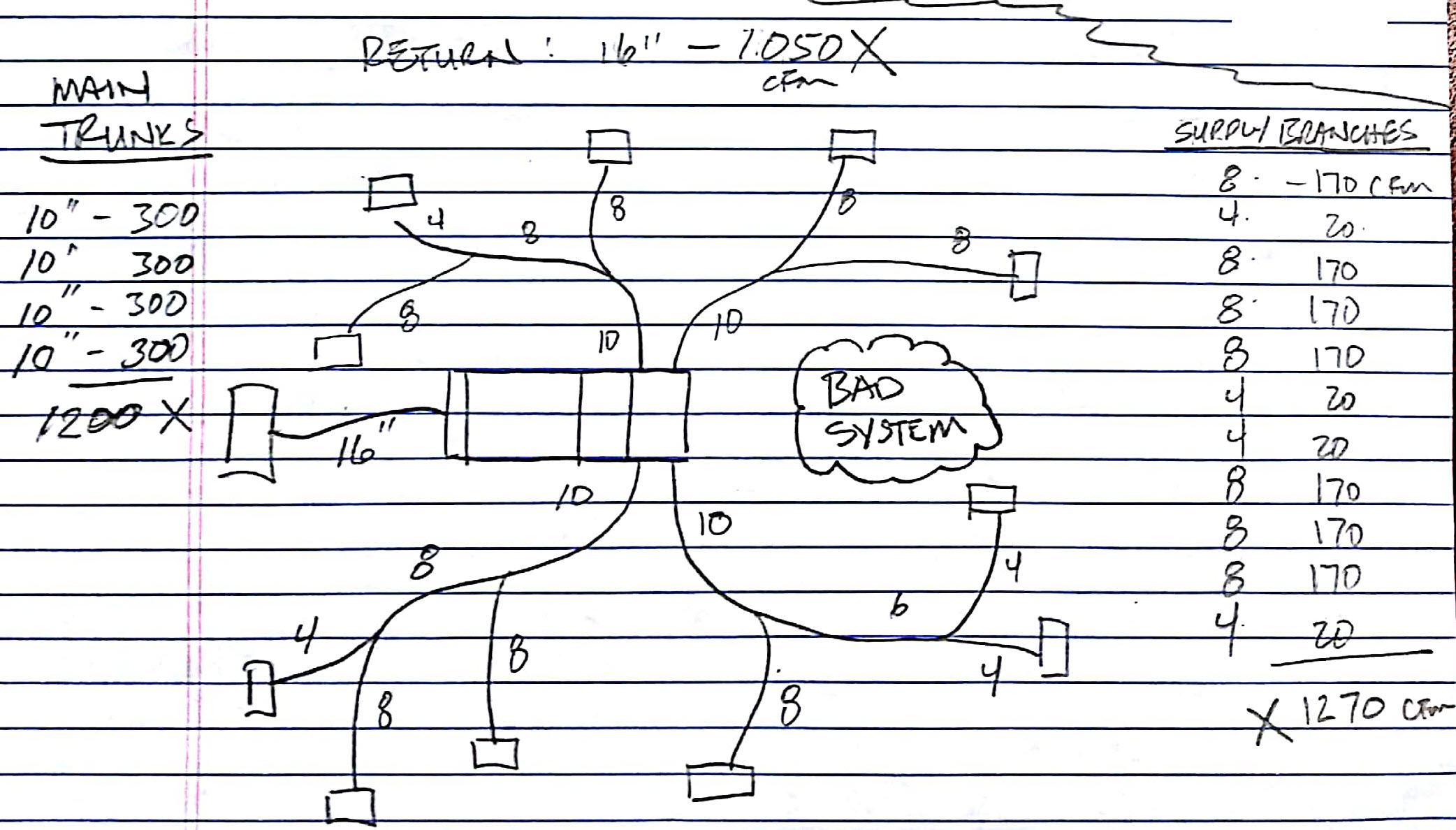
Something I get asked to do on a regular basis is take a look at a duct layout for someone’s house and see if it “looks OK”. Here is a good example. Suppose someone showed you this sketch of a 3.5 ton system and said, “Does this look OK to you?” You might look each trunk/branch combination and say, “a 10″ serving two 8″ ducts, that seem OK. A 16” return duct on a 3.5 ton, that seems reasonable. Each run might look reasonable and there are registers in all of the rooms, but the main question should be, “Will ALL of the ducts handle ALL of the air?”

In about 10 minutes I can tell you if there are any serious problems related to duct sizing. Here is how I do it.

Table 1 – Duct Size vs. Airflow at a Friction Rate of 0.1
1. Figure out how much air is the system is supposed to handle. I usually use 400 cfm per ton (condenser tonnage) as a minimum. If the designer tells you a higher number, use that.
2. Are there enough supply trunks to handle this much air? List the diameters of all the start collars coming off of the supply plenum. Use the airflow table, right. This table represents how much air a certain size duct should handle in a “reasonably well-designed” system (friction rate = 0.10 iwc/100ft). Add up all of the flows – they should be greater than the target flow (from #1).
3. Are there enough supply branch runouts to handle this much air? Repeat step 2 for the supply branches (ducts that serve a single supply register).
4. Are there enough return ducts to handle this much air? Repeat step 2 for the return ducts.
This test will not tell you if the equipment is over or undersized, nor will it tell you how well the system is balanced – whether the air is going to rooms in the right amounts, relative to other rooms, but it will quickly identify one of the most common problems: undersized ducts that impact overall airflow to the system.
Let’s do it for this sketch: The target airflow would be 3.5 x 400 =1400 cfm. The four main trunks add up to 1200 cfm – NOT GOOD. The supply branch runouts add up to 1270 cfm – NOT GOOD. I frequently see 16″ returns on 3.5 and even 4 ton systems. A 16″ duct should only handle about 1050 cfm – VERY BAD. This system would run at a much higher static pressure and probably would not pass the minimum air flow and maximum fan watt draw test of CA’s Title 24 energy code (350 cfm/ton and 0.58 watts/cfm) and those are not meant to be hard numbers to beat, but far too few installers know how to properly size ducts. Some even take the time to use Wrightsoft or Elite Manual J/S/D software but then have some hidden setting in them that messes everything up. (See my article about why we need a simpler Design Methodology). Most installers just use old rules of thumb that result in these substandard systems. Kudos to those who actually do a good job. Their numbers are growing, but far too slowly.
If they had used a better design methodology they might have come up with this revised version of the same plan. The revised layout passes this quick test. The four main trunks add up to 1800 cfm, which is good. The supply branch runouts add up to 1480 cfm, which is close, but OK. The return is a 20″, which can handle 1875 cfm, which is very good. Note that an 18″ duct would barely work. The intermediate “trunks” can be checked independently in a similar manner. This layout will probably work just fine, at least in terms of delivering 1400 cfm. Something that I have found to be true in many cases is that very good overall airflow will forgive a lot of sins, including minor balance issues and even minor over or under-sizing of equipment. It’s not that hard to do, folks!

 HVAC 1.0 Book – Introduction to Residential HVAC Systems
 Kwik Model 3D HVAC Design Software
Sep 30, 2017 @ 15:48:38
Russ, I really like your simplified approach. I believe every installer or designer should keep a copy of your duct sizing table in his/her wallet. Regarding the returns, I am in the school of reducing the velocity to the 400 fpm range. This would require 2 returns instead of 1. I use Table 150.0-C in the CA Energy Code/Standards as a quick guide and it seems to work well. A 3.5 ton system would use two 16″ returns to slow the air down and reduce the noise. The grille area in this case is min. 1000 sq. in.
Oct 05, 2017 @ 06:59:39
Thanks, Roy. Bigger is definitely better for returns. My approach is to determine if it meets the minimum requirements of an “acceptable” system. Guidelines such as the one you suggest are to help you design a “very good” system, so more power to you!
Jul 03, 2018 @ 09:18:56
A/C tech tells me that I donthave enough return. Can I branch an additional return to my system? My current return is 18″x20″ for a 4ton system.
Jul 03, 2018 @ 12:18:54
Yes, definitely. Assuming you have the room to attach more ducts, more return airflow is always better. You can either increase the size of the existing return duct and grille or add more.
Good luck!
Nov 14, 2022 @ 18:20:09
How can you connect a 20″ duct to a package unit when the unit itself has a 14×17 opening for the return?
Nov 14, 2022 @ 19:52:41
With a sheet metal transition piece. 20 round to 14×17 rectangular. It will have to be field fabricated and custom, but it will work. Just because the opening is smaller than the duct doesn’t mean you can’t connect a larger duct to it. The resistance to airflow through the duct depends on the size of the duct. Air flowing through a larger duct (even before or after going through a small opening) will have less resistance than a air flowing through a smaller duct.
Aug 07, 2018 @ 13:37:35
Russell,
In you updated calculations; you added 12″ (500cfm) supply that is branched to 9″ (230 cfm) and 8″ (170cfm). That is total 400cfm. So if 500cfm is coming out and you have only 400cfm that can go through; how the system would behave? Please elaborate. Thank you.
Aug 08, 2018 @ 07:51:53
Hello!
Great question. The way to think of those numbers is not as how much air is coming out, but how much air can they handle. When you do a full ACCA Manual J/S/D design you have airflow targets for each room. You size a duct to each room that has the ability to handle at least as much as you need. When a trunk serves two branches you size the trunk so that it can handle at least as much as the total of the two branches. So, putting the 12″ on there ensures that there is at least 500 for the branches (they need 400). Had I only put a 10″ on there, it would only handle 300 and the branches would be under served. The 10″ would have been a bottleneck.
You should always pick the next larger size, just above your target. It’s interesting when you look at the duct size vs. airflow table how big of a difference there is between a size and the next size up. Going from a 6″ to a 7″, for example, is a 50% increase in airflow capacity. That tells you two things: 1. rounding up one size is very safe. 2. undersizing by just one size can be very bad. When you do it correctly, what ends up happening when you turn the system on is that it will end up delivering a bit more air overall than you designed for, and that is always a good thing. Some rooms may be a little more than you need and some may be a lot more than you need, but it is much easier to damper the airflow down than to try and increase it.
Thanks for the question.
Russ
Nov 28, 2018 @ 22:46:40
Hi Russ. Thanks for posting this information. I just had a new system and duct work installed but I’m double checking the job. I feel like its missing an extra return. I live in Los Angeles in a 2200 sq ft split level with a 5 ton day and night system. I have 2 returns (12″ and 16″) so providing 1550. Output at box (12″, 9″ and 14″) so providing 1470. Out at registers at 1500. Based on the info given, I need about 450 more in return and more registers to balance everything out at 2000?
Thanks for the help. I drew everything out if that helps. I can email it over to you.
Fred
Nov 29, 2018 @ 09:06:58
Hi Fred,
Are you sure it’s a 5-ton system? That actually sounds really big for that size house, especially in a mild climate like LA. Please feel free to send me a layout. I’ll take a look at it. russking@sierrabuildingscience.com
Russ
May 23, 2019 @ 10:41:35
This is fantastic information. I had a new unit installed on the old unit’s duct work and the installers did a pretty weak job. I’ve had to go back and seal up most of the connections to the supply plenum and my next project is to move the condensate trap vent they put on the wrong side of the trap. I’ve been double checking everything else they did to be sure there aren’t any other hidden issues, like how they taped over the insulation they replaced on the refrigerant line and didn’t tell me a mouse chewed through the old stuff and it corroded/failed causing the old unit to die. Luckily I caught that on the second old unit before it could fail (both insulation sleeves were chewed up but the downstairs ran more often and thus condensed more water on it) but they should have mentioned it so I could have caught it earlier before it began to corrode. Now I think I might go through and calculate air flow like you show and see if the flow is anywhere near correct. The devil really is in the ductwork!
Jun 28, 2019 @ 07:41:24
Russ,
I enjoy your website and insights from the design perspective. I’m a Service Manager for an HVAC contractor in Atlanta. The airflow chart you listed lists different numbers than a standard “ductalator” at .1″ static. For example, 10″ round duct should move @ 400 CFM at .1″ W.C. according to the ductalator. How did you arrive at 300 CFM on your chart?
I appreciate your time.
Brian
Jun 28, 2019 @ 10:29:15
Hi Brian,
Thanks for checking in. Great question. Sounds like your ductulator is for round sheet metal. My table is for vinyl flex duct. I’ve found that round sheet metal ducts will give you almost the same airflow as a flex duct that is one inch diameter bigger. I usually use ACCA’s duct sizing calculator/wheel. It has metal, flex, ductboard, and duct liner on it. My numbers in the table are based on an average between ACCA’s and a couple other brand-specific ductulators I found. It’s odd that they don’t all give the same answer for flex duct, but they are pretty close. When in doubt, round up!
Russ
Jul 02, 2019 @ 16:55:06
Russ,
Thanks for the quick response and the explanation. I’ve binged this whole site and am going to use some of this information in our next service meeting. Is your book similar to the information on this website? Thanks again.
Brian
Jul 02, 2019 @ 17:53:16
Hi Brian,
I’m glad you found this site useful. My book is very similar. In fact, several of the articles are straight from the book. It is intended for people who need to work “around” HVAC systems, but not necessarily have to work “on” them. 90% of my experience is in the hotter parts of CA and NV, so the terminology may be a little different and I absolutely do not cover any humidity issues. It’s used in at least two community college HVAC and construction programs. I think you’ll find it interesting.
Thanks
Russ
Jan 07, 2020 @ 13:52:09
Russ,
Very helpful information. Very clear and easy to apply.
I was working with a Ductulator, and I was comparing Its diameters and flows against “Table 1 – Duct Size vs. Airflow at a Friction Rate of 0.1” and I got 0.055 inW.C./ 100 feet on my Ductulator against the 0.1 inW.C./ 100 that the Table 1 indicates.
I am doing something wrong, or Table 1 considers round ducts with significant more friction?
Thanks,
Carlos Cirera
Jan 07, 2020 @ 21:53:16
Hi Carlos,
Thanks for your question. My tables are specifically for round vinyl flex duct. Check your ductulator. It sounds like it might be for sheet metal ducts. I really like the “duct wheel” that ACCA puts out because it has both, plus a lot more features. Generally speaking you will get about one size smaller for sheet metal vs. flex. In other words a 7″ round sheet metal duct will move about the same air as an 8″ round flex.
Russ
Jun 19, 2020 @ 20:14:34
Hi Mr. Russ,
I have a very similar setup to the example you gave. I just had a new 3.5 ton 16 SEER condenser installed with evaporator coil and ducts attached to a 3-4 yr old 14 SEER furnace. It’s alright. I’m not buying a new furnace. I’m not sure of the diameter of the ducts but I think they’re pretty close to your “bad system” sketch, 8″ and 10″. 11 registers total. 1 story home 1774sq ft. I didn’t find your site until now. What’s done is done, but my question is about the return air. The contractors pulled out my 35 yr old 12 or 14″ return duct and dashboard and replaced it with a short 16″ return air in the attic only and sealed it well in the attic. They did not extend it down into the house like before. Left the wall cavity where the duct used to be empty, nothing in the wall cavity just the drywall and studs used for the return air, but come to find out it’s a common industry practice on low priced jobs. I don’t know if condensation will accumulate on the cavity walls. It’s an interior wall in the hall by a bathroom and bedroom. The new air flow in the home is powerful, but now it’s loud in the adjacent bathroom. I’m worried about not having a return duct. I read it could be a fire hazard or could cause mold in a few years with the humid Houston, TX weather. Therefore I’m more inclined to put a duct but I don’t know if 16″ is enough, if 18″ is that much better, or just leave it the way it is with the cavity as the RA. 18″ would be better but there is a 2×4 stud in the attic in the way and would require modification to fit the 18″. I was told by another AC contractor a while ago to install a second return air. I feel that would be too much for my small to average one story home and would be another cost to incur. I could use your advice. Please share your thoughts on my situation. Thank you for your time. Kind regards,
Basil
Jun 22, 2020 @ 07:14:31
Hi Basil,
Increasing return air capacity is a good way to improve overall airflow. Your fan is like a locomotive that is near the center of the train and is both pushing and pulling cars. A fan is pushing air through the supply ducts and pulling air through the return ducts. If you lighten the load on either side, it will work better. Regarding the unducted return, it’s not great, but it’s not horrible unless it’s pulling air from somewhere bad. They tend to be very leaky. It just depends on where the leaks are coming from. Mold is not a particular issue on the return side because the temperature of the return air will always be about the same as the house, or warmer if leaking from the outside. You never ever want to blow cool supply air through unducted building cavities because the cold air could cause the materials to go below the dew point and then moisture will condense. If your choice is between good return airflow with the unducted return, or reducing the airflow by running a duct through it to make it less leaky, if the unducted return is tight or just leaking a little to conditioned space, I would say it’s probably fine. If it’s really leaky, you should run the duct as big as possible or try to line it with sheet metal. There are people who will test your ducts for leakage. Search around for “HERS raters” in your area. Some HVAC contractors (far too few) have duct testing equipment, commonly called a “duct blaster”. Lastly, If you have any gas burning appliances (especially a furnace or water heater) inside the conditioned shell of the house, always have them tested for back drafting and combustion safety after doing any major work to your system. Making big changes to your duct system can create unexpected pressure differences in your house. Return leaks to outside will cause a house to pressurize. Supply leaks to outside will cause a house to depressurize.
Good luck!
Russ
Sep 10, 2020 @ 10:52:22
Hi Russ,
We bought our house ~5 years ago. The first summer I found the upstairs hvac would run nonstop and only be able to maintain 78. We had to replace the downstairs unit early that same year so I called the company that replaced it to take a look. Their immediate answer was that the unit was too small and we should upgrade the 2 ton to a 2.5 ton unit. I was very bothered by this answer for some reason and started researching hvac a lot. That’s when I ran into your blog and this post specifically. After reading it I went up into our attic to take a look at the ducts. The main branches were two 9″ flex ducts and the only return was a single 14″ flex duct. I couldn’t believe how far off it was. Basically our 2 ton assuming a need of at least 800cfm was getting choked down to 460cfm or half the required minimum. To make it worse. The final supplies were four 8″ flex and two 5″ flex (780cfm).
I used the information here and ended up changing the main branches to two 12″ flex ducts among other changes to supply lines, the return I changed to a 16″, and later ran a separate 10″ return to the bedroom with the thermostat since the rooms would get pressurized when the doors were closed. I then changed two of the 8″ supplies to 9″ supplies for the two larger areas along with larger grilles to match the 9″ supply. Now the supplies total 870cfm. Since then the unit can at least keep up with around 72 degrees at least on hot summer days. While changing the ducts out I also found they hadn’t sealed the connections hardly at all. The return they had bent the tabs short and randomly screwed them at the top of the plenum thus sucking air directly from the attic.
All of the above changes I viewed as a temporary fix. Since the hvac unit is in the attic, and our attic gets very hot, I would like to replace and move the air handler into a linen closet near where it is now and possibly replace most of the duct work and then seal it all in spray foam since there is no other area planned for the ducts. This would also allow me to centralize the return air filter. Currently our system uses all flex duct with fiber boxes in an octopus layout. I would like to change the main lines to metal duct using straighter runs and then connect to the existing flex duct only leaving around 6′ or less of flex at each supply. In this case since I would be changing to metal would there be any concern of the ducts being too large? and is that generally a problem. Based on the math you present here it seems like it would work fine as I’ve added up the branches and main supplies. The main branches would be 1050cfm and the final supplies would be 870cfm. The returns would be the same 16″ and 10″ flex but I plan to add pass through vents for the other two rooms.
I can’t thank you enough for sharing this information and how much it really helped me out. So sincerely thank you.
-Greg
Sep 10, 2020 @ 11:29:48
Wow, Greg! Thanks so much for checking back in and letting me know that this worked for you. I really appreciate it. I’m so glad it helped you out. I hope more people will see your comment and decide to give it a try .
Regarding your proposed changes, they all sound like improvements, but whether the improvements justify the costs is the question. Flex duct gets a bad reputation due to poor installation practices. It does have some advantages: less joints have to be sealed; a long gradual bend has less resistance than a sharp 90 deg bend, the insulation has a vapor barrier over it, things like that. If installed correctly the only real disadvantage is more resistance to airflow for a given diameter, but this is more than compensated for by just going up a size. If you were really limited on space then sheet metal would be the obvious choice. A few things to keep in mind: 1. Moving your furnace into a closet might add elbows to the supplies and returns and might cause space issues for ducts. 2. You can do things to make your attic cooler: add passive and active attic vents (fans), radiant barrier, under-roof-deck insulation (different than encapsulated attic – search for “high performance attic option b” – basically a super duper radiant barrier). This helps your ducts but also reduces heat gain through your ceiling. 3. within reason, ducts can’t be too big. Better airflow fixes so many problems that the disadvantage (more surface are and slower velocity means more conductive heat gain from attic) is usually outweighed, especially on the return side. 4. Make your return air filter as big as possible. This is one of the main design failures (other than under-sizing ducts) that restricts airflow. Bigger is better for filters – less resistance, better filtration, less noise, filters last longer, etc.
Good luck! Thanks again for the feedback.
Russ
Sep 21, 2020 @ 06:45:35
Hi Russ,
Thanks for the reply. I read it last week but haven’t had a chance to follow up. You brought up some very interesting ideas. I’ve considered doing a radiant barrier recently but the under deck insulation is an interesting idea. You brought up some good points on maybe keeping the flex duct in place and using it. A couple follow up questions.
1. Our system now uses fiber boxes for the transitions. I’ve read a little that those can introduce fiber particles into the air. Are those boxes safe to keep in place? Also how long do they last? Our house is around 15 years old now.
2. How long does flex duct last?
3. For the Air filter I was thinking of using Aprilaire’s media cleaner (model 1910). It’s a 25″ x 20″ x 4″ merv 11 or merv 13. I should have room to do this. Any thoughts on size or on Aprilaire’s media cleaners? It sounds like they cause less resistance and last longer given the 4″ depth which would mean less filter changes and better filtration.
thanks again,
Greg
Dec 30, 2020 @ 07:33:01
Hi Russ,
Appreciate this article. Very very useful. I live in Houston and ran into this 2 story home approximately 2,100 sq. ft. House has (2) 3 ton systems. One of the systems recently has had new ducts installed. I’m looking to install new ducts on the other one. After checking everything out I noticed, this system has a 14″ return and only has (3) 8″ supplies and (1) 6″. From the chart above that equals 590 cfm. Any idea why they would do that. This is an upflow system with a short plenum due to clearance on the rafters. From the plenum they attached a 14″x14″ trunk out of ductboard. From this trunk they came out with (2) 8″ ducts. Then the trunk reduces to 12″x12″ and from this trunk they came out with the other 8″ and 6″ ducts. I was thinking maybe it was due to friction loss (love your article “Friction rate Explained”) through the ductboard trunks and because there is no turning vanes on the plenum but I find it hard to believe since it only has (4) elbows and the total length of the trunk is roughly 40′. I would love to get your opinion on this. Thanks and please share the name of your books and where I can find them. Thanks again.
Juan
Dec 30, 2020 @ 08:12:14
Hi Juan,
Thanks for your comments and questions. You asked, “Any idea why they would do that?” Honestly, I have no kind answer, but I was not the one sweating in the Houston humidity trying to make the ducts fit. Usually, it’s just because they don’t know any better, but it could also be because they only had so much room to work with. (I’m definitely giving them the benefit of the doubt). Those ducts are definitely undersized for a 3 ton system. At first glance, it seems that your equipment is oversized, but one would have to do load calculations to know for sure. Oversized equipment and undersized ducts are far too common and the cause of a lot of comfort issues and high energy bills. The 14×14 is what they figured they needed to handle all of the air. It’s a bit small for a 3 ton, but not as bad as the 14″ round return. Once a couple 8″ ducts come off of it, it doesn’t have to handle as much air, so they drop it down to 12×12. If the supply branches were properly sized, reducing the trunk helps prevent the air from screaming past the first few take offs and favoring the take offs down at the end. Turning vanes are not very common in residential systems, but they would help alleviate this problem too. When the branches are severely undersized it really doesn’t matter, there’s so much static pressure in the trunk that the air is just looking for ways to get out.
The name of my book is “HVAC 1.0 – Introduction to Residential HVAC Systems”. It can be found on Amazon or http://www.sierrabuildingscience.com
Thanks! Good luck with that house.
Russ
Feb 02, 2021 @ 07:09:12
Why would you ever just put 1 return in a home. That is a horrible design
Feb 02, 2021 @ 08:44:46
Hi Kevin,
Returns are overrated. A well designed system only needs one return. Supply air is what makes a house comfortable, not return air. Check out this little video that shows the difference. I’ve designed and tested thousands of homes with only one return and they worked great, even two story homes. In fact they worked 10x better than a lot of houses with multiple returns. Adding returns is often a bandaid for oversized equipment and poor supply duct design.
Russ
Feb 09, 2021 @ 15:18:37
Howdy Russ,
While digging into why one of our rooms gets no heat(Takeoff is next to the endcap and not far enough away from the next takeoff) it lead me down a rabbit hole of duct sizing which lead me here. We have a small ranch home in region 5 with a 60000 BTU furnace and what is worrying me after looking at your diagrams is we only have x10 6in supply branches feeding 12in x 4in registers. If I’m understanding you correctly here, and, I wanted to keep the current locations for everything I would need to increase the 6in supply branches to 10in? From what I’m seeing, boot diameters don’t even go that high. Would this mean I’d need to add registers to each room so I can reduce the ducting size?
Feb 09, 2021 @ 15:44:54
Hi Jim,
It doesn’t sound like your system has AC. This article is primarily for systems with air conditioning. Sorry if that was not clear.
Furnace systems without AC usually run on a much lower fan speed and are much less susceptible to low airflow issues. What typically happens with really low overall airflow is the air moves too slowly across the heat exchanger and gets too hot and sets off the temperature rise limit switch. The whole thing will just stop. However, improving overall airflow will generally improve comfort. If you have more air going through the heat exchanger, the supply air won’t be so hot, even though it will be delivering more btus. The less hot the supply air is, the less likely it is to stratify, plus the higher the airflow will improve mixing. Mixing is key to comfort. You want the supply air to mix in and become one with the room air as quickly and efficiently as possible.
Do you know if you have a variable speed or single speed furnace? One very easy fix for single speed furnaces to try is to have a technician set the “speed tap” to the next higher speed. This might increase noise a little bit, but it will push more air through the ducts.
What heat-only systems are very prone to is poor balance, which is exactly what your problem sounds like. The rooms are not heating evenly. The best way to solve that is to do room by room load calculations on the house so you can determine how to distribute the air. If a room is 10% of the load, it should get 10% of the air. Once you have the airflow targets, you can measure the actual airflows and see which rooms are getting too much air and which rooms are not getting enough. Then go from there. Of course, that’s a lot work and requires special software and expertise. The more common way is to just try a bunch of things until it gets better! It’s far better to try to increase airflow to low rooms than to reduce airflow to high rooms. Adding ducts and enlarging existing ducts are much better than closing registers to force air to other rooms.
I hope this helps.
Feb 09, 2021 @ 16:12:51
Whew, well that’s a load off my mind, haha. It is split system central air, I think the AC is 1.5-2 tons which looks like our system would be fine according to your diagrams.
I’ve actually done the trial and error method with the dampers trying to force heat to that room which has me completely closing 5 of our 10 supply branches and partially closing the others that still need the heat which only resulted in a 2 degree increase in that room(Thermostat set to 70°, room was 66° and is now 68° after the trial and error.). I’m really hoping increasing the length of the duct to move the endcap further away from the takeoff will fix the issue and I’ll be able to open the dampers back up because those 2° came at the expense of heat in one of the bedrooms, haha.
Thank you very much for the response. Although I misinterpreted this blog post the info is the best I’ve seen thus far, keep up the great work.
Jul 24, 2021 @ 06:23:31
Hi, your layout seems very helpful for me, I was looking for a residential HVAC duct blog & came across this one which seems to be very interesting.
Jul 24, 2021 @ 08:53:09
Hi. Welcome. I hope you get something out of it. Feel free to ask questions. If you design residential HVAC systems, you might also be interested in our software Kwik Model with EnergyGauge Loads. Check out http://www.kwikmodel.com and our YouTube Channel: https://www.youtube.com/channel/UC7HM3nJWOE5_Om0nMBfKj7w/videos
Oct 10, 2021 @ 13:38:57
Russ. Just found your eye-opening site. Kudo’s to you Sir. I’m a new built house owner and have been looking at the attic located ductwork. The house is foam “encapsulated” (foam sprayed to the underside of the roof).
I’m not too impressed with the ductwork (all flex). First question. The A/C is a 4 ton unit. Using the numbers you provide, the estimated CFM should be 1600 (4 ton x 400 cfm per ton). The return ducting is 1ea 16″, 1 ea 10″ and 2ea 4″ that for the life of me don’t understand are routed to the soffit where they both draw outside air. My math says that the TOTAL return side CFM is 1390 CFM.
Can I assume that my return is undersized by about 200 CFM? Before I start doing something that I perhaps shouldn’t should I be concerned?
Oct 10, 2021 @ 18:19:24
HI Lester. I sent you an email.
Dec 03, 2023 @ 19:44:44
Russ, this is Linda from Colorado, I’m buying a newly built house,
Builder put ducting inside closet, separated ducting with drywall.
The bedroom including closet in the plan is 162 soft, we are arguing on ducting space taken from closet, left closet tiny.
Hope we know from an expert if ducting room is part of closet by law.
Dec 04, 2023 @ 17:55:00
Hi Linda,
There are codes that say that an HVAC system including the ducts must be properly designed and installed. This sometimes means that you will have to sacrifice a dead corner or two in your home in order to accommodate those ducts. These are called “chases”. The builder will box out a dead corner in a wall so that ducts can be routed to different parts of the house. Without these, you would not be able to condition parts of the home properly. It’s sometimes unfortunate, but depending on architectural layout and structural constraints, they are a necessary feature, There is no code that says you have to have certain size closets. In my opinion, comfort and energy efficiency are far more important that closet space.
Russ
May 01, 2024 @ 08:29:55
Hi Russ, I had new coil/furnace/plenums and all new ductwork installed. It is all flex duct but want to now switch it out for metal duct. Do you know how I figure the different sizes to switch to metal duct (as I read they are more efficient so are generally sized smaller)? Also I have one large return in the living room and one small return in the master but no other returns and wonder if I need more returns (1887 sq ft house, 3 bedroom) I’ve been trying for months to find some counsel on this with little success.
May 06, 2024 @ 14:39:01
Hi Rose,
Why do you want to change out the ducts? Are you having comfort issues? If properly sized and well installed flex duct can actually outperform sheet metal duct is some ways. In a side by side test, round sheet metal will deliver about the same airflow as one size larger flex duct. In other words a 6″ sheet metal duct will deliver about the same as a 7″ flex duct. However, the way most sheet metal systems are laid out, they often have more equivalent lengths due to the sharp angles and end up having to go a size larger to compensate.
Russ
Jul 23, 2024 @ 19:03:49
Hello Russ, I just came across this post and find it very handy. I have a few questions to ask you as I’m continuing to gain more knowledge in the industry. I realize this was posted a long time ago but I would love your help! Thanks in advance.
Jul 23, 2024 @ 20:00:12
Hi Carlos. I can be reached at kwikmodel@gmail.com.
Russ
Nov 12, 2024 @ 11:58:20
I am in the process of getting my HVAC system swapped out. I have a couple of contractors saying the flex ducts that are in the attic are undersized and then others that say things are completely fine. As I search the internet for CFM rates for diff sized flex duct, I see 14″(650 cfm), 8″ (150 cfm), 6″ (70 cfm). Sometimes I see something slightly diff. When I “challenge” a couple of the contractors, they tell me the cfms are much higher for the size ducts. For example, one contractor says 14″ is 850, 8″ is 225 and 6″ is 120. If I use their numbers, then I have enough CFM. How can they have such diff CFM numbers from what almost seems to be “unanimous” when I search and I cannot find anything to support what they are telling me?
Nov 13, 2024 @ 06:12:42
Hi Jason. Thanks for your question. Two words: Friction Rate. That plus duct diameter is what determines airflow. FR describes how much pressure is available to push the air down the ducts. For really long runs there is less pressure, so you will get less air, for short runs you will get more air through the same size run. In this example, I used a FR of 0.1, which is pretty common for a simple duct system. More elaborate systems will have lower friction rates (less air through the same size ducts). I have another blog article specifically on this topic. Here is a link: https://russellking.me/2020/07/05/friction-rate-explained-maybe/
Nov 20, 2024 @ 15:43:14
Hi Russ, I want to replace my 15 yr old HVAC system and very much appreciate the insight from your web page! House is 2800 sq-ft with existing 5-ton AC/Heat pump. The existing system has gone through 2 compressors & 3 evaporator coil units during its 15-year lifespan. In getting replacement quotes, the opinions are varied on duct sizing & why the existing system has failed so many times. Using your calculations, here are the results for my system: (1) 400cfm x 5 tons = 2000 cfm (2) supply trunks: 12+12+10+9 = 1530 cfm (3) supply runouts = 1470 cfm (4) return ducts = 1790 cfm So, I see some issues, given your method. Is it reasonable to ask for a system air flow design as part of requesting a price quote for a new system?
Nov 20, 2024 @ 21:07:52
Hi Bob,
Yes. Absolutely. I see issues, too. They could easily check the static pressure across the fan to see if it is within recommended range. Also, it would be reasonable to ask them to do a load calculation to justify the sizing of the system. It’s entirely possible that 5-tons is too big. One common cause of compressor failure is short-cycling, caused by oversized equipment – kind of like city driving, as opposed to freeway driving. If you decide to keep the 5-ton, definitely have them improve the airflow capacity.
Good luck!
Russ
Aug 31, 2025 @ 09:59:34
Hi Russ, I have a five year-old home that is fully encapsulated with spray foam. The attic has open cell spray foam. This whole journey started with high humidity in the attic. While trying to figure out what to do, I asked a few questions on Reddit and a responder started asking questions about my duct sizes. I finally determined my return and main supply ducts are undersized after finding your blog. I have a 3 1/2 ton AC unit with 80,000 BTU furnace. The return is a single 16 inch flex duct about 20 foot long. The supply is a Plenum with two main supply ducts, one is a 12 inch metal duct with 10 run outs and a 10 inch metal dut with six run outs there are also 2 x 4 inch elbows coming off the Plenum and the original 12 inch metal duct supplying conditioned air to the crawlspace. The attic does not have any conditioned air and that’s why I believe I have high humidity up there. I would like to build a Plenum for the return side and add an Aprilaire 4 inch media filter and add a 12 inch return the reinstall the 16 inch return. On the supply sign I would like to cut in and add an additional 12 inch metal duct into the plenum and remove four of the run outs from the original 12 inch metal duct and move them to the new 12” etal duct. I would also like to add a 6 inch supply off the original 12 inch metal pipe to run up to the attic. The issue I am having is I have had three HVAC companies come out and look and I get opinions all over the place. One guy measured my static pressure across my fan, but took the supply side reading after the coil and according to the fan curve, it should’ve been taken before the coil and after the furnace. Also, the fan speed wire was on a lower fan speed that cannot develop 1400 cfm according to the fan curve. Do you see any issues with what I am trying to do or have any suggestions. Thanks Barry
Sep 01, 2025 @ 21:52:05
Hi Barry,
That is a lot to digest without a sketch, but I think you are going in the right direction. You cannot oversize a return duct or filter. Go as big as you dare! Going a size or two larger on supply ducts will certainly help. Also see my article about improving airflow with better supply registers.
Re: the humid attic, that’s a tricky issue. See my article about “Conditioned Attics”. Dedicated dehumidifiers seem to be the way to go in humid climates.
Good luck!
Russ